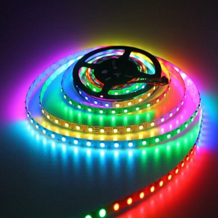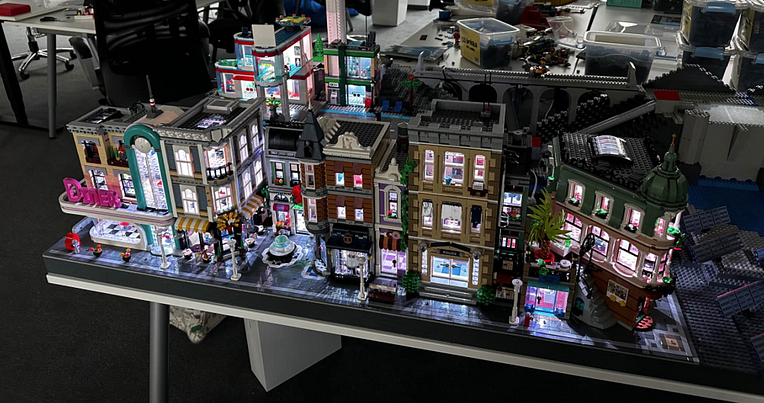
Last year the company I’m working for, was requested to create a sample for an IIoT (Industrial Internet of Things) use case. We’ve built a LEGO® model with a few houses. The light was controlled by an application which took weather data to simulate wind and solar power. The light controller was, just as prototype, a Raspberry Pi connected with a WS2812b LED-Strip.

These LEDs are controllable by software, so we were able to set up the light in any LEGO® building different. Why should we do this? Simple answer: not any household uses the same light, so why should we do this in a model of a small town? 😄

This project got me thinking about to use LED lights instead of
fireworks for the New Year’s Eve party 2023. This post will describe
what I did and what my main issues were.
Prerequisites
Firstly, we need the hardware
- A Raspberry Pi (I use a Pi 2 Model B v1.1)
- For a better handling, a GPIO Hat
- A W2812b Led-Strip
- And a power supply 5V, 2500mA output
(The Pi 2 needs a Wifi module if you like to control it wireless. 😉)
Secondly, the software
- The OS for the RPi is Linux 10 (Buster)
- Application is developed in C# (.NET 6.0.402)
Wiring
In the past, I’ve learned in a RPi project to describe the wiring. The most interesting part in this project here, actually all documented wiring were wrong. For example, this documentation here uses pin 18. The same pin is used in many other documentations, but in my case, pin 18 is wrong. If I use it, nothing will happen.
Why is it so?
I think the reason is the program language. All the samples are developed in Python and uses the lib neopixel, which is different in C#.

In C# I use a SpiDevice. So I have to look for a different pin, related to the SPI pins. Luckily, I found a very helpful description of any pin here
and after reading a lot about SPI, I found out I need to take the pin
21, which is the GPIO 9, which is the SPI0 (zero), which is the MISO
(master in slave out) pin. 😱
So many different names. It was absolute horrible for someone who wants just turn on some light.
Finally, the wiring result is:
- Pin 4: 5V
- Pin 6: Ground
- Pin 21: Signal (called Din on the strip)
Because I used the GPIO Hat, it was way simpler to connect the wire.
Software
After putting all the thing together I started to develop the application. My first version was a command line application, starting a sequence of effects. But now it is a web application to control the light via WebAPI.
I don't want to describe how to set up a WebAPI project in .NET. Also, I don’t want to describe how to develop an API Controller. The interesting part is the LED Service aka LED Strip.
To control the light, you need four namespaces:

You get it by referencing the NuGet packages Iot.Device.Bindings and System.Device.Gpio.
To set up a SPI device, you need to know which busId is connected and which chipSelectLine
is in use. 🤔Yes I had the same questions, what is a busId and
chipSelectLine. To be honest I don’t know, but luckily I used Linux for a
while and after a few error messages from the SpiDevice
I remembered me where to find out the SPI device settings. Actually not
exactly the SPI device settings but the connected devices. You can
enter ls /dev/ in your Raspberry Pi terminal, and you will get the whole list of connected devices.

In the screenshot, you can see all my connected devices, also the spidev0.0 and spidev0.1. After testing a lot, I found out that the numbers are the busId (0) and the chipSelectionLine (1) for the MISO pin. Crazy, isn’t it?
All that experiments led me to get the right setting for the SpiDevice.
SpiConnectionSettings spiSettings = new (0, 1)
{
    ClockFrequency = 2_400_000,
    Mode = SpiMode.Mode0,
    DataBitLength = 8
};
The setting ClockFrequency, Mode and DataBitLength values are just a copy by a sample developed in Python, but it works. 😉
To initialize a Ws2812b LED strip, we need the SpiConnectionSettings and the length of the strip, which means the number of LEDs the strip have. In my case, I have 60 LEDs to control, one meter. If you want to control more than one meter, count the LEDs.
BTW, the power (5V) of the RPi is good enough for one or two meter, but if you need longer strips you need more power. The Ws2812b strip provides for any part a red and white cable. Here you can connect a power supply to support the LEDs.The constructor of my LedStrip class expects the SpiConnectionSetting and the number of LEDs. Here the
SpiDevice will be created and assigned to an internal variable _ledStrip which is type of Ws2812b.using Iot.Device.Graphics;
using Iot.Device.Ws28xx;
using System.Device.Spi;
using System.Drawing;
namespace LedStripControllerApi.Services;
internal class LedStrip : ILedStrip
{
private int _numberOfLeds;
private Ws2812b _ledStrip;
public LedStrip(SpiConnectionSettings spiSettings, int numberOfLeds)
{
SpiDevice spiDevice = SpiDevice.Create(spiSettings);
_numberOfLeds = numberOfLeds;
_ledStrip = new (spiDevice, numberOfLeds);
}
...
}
So, the biggest part of magic is happened. The LED strip is connected and the SPI device is initialized. Now we can take a short look into one effect, just turn on the light.
public void TurnOn(Color color)
{
  // turn off all led
  Clear();

  // get the image of strip
  BitmapImage image = _ledStrip.Image;

  // iterate through led and set the color of the pixel
  for(int i = 0; i <= _numberOfLeds; i++){
      image.SetPixel(i, 0, color);
  }

  // update the data
  _ledStrip.Update();
}
In the snipped, you can see that a LED strip will be controlled by an image and its pixel. Any pixel represents a LED. Because we have just a single line strip, the SetPixel method uses 0 as y-coordinate.
To control the image, you have to put the image in a variable before changing. I tried it to change it directly but without any result, so don’t wonder, just do it the same way. 😄
Finally, after set all pixel, aka LED, of the strip, you need to update the Ws2812b instance. You don’t need to reassign the image, it is still referenced.
Good news: Here you will find the whole project. Clone it, fork it, use it.